3D measurement technology
Creates 3D data from digital camera photos. Principles of camera mechanics and triangulation are applied.
In general, when measuring an object using cubic data, the measurement is made with five corresponding points in two photos taken from different viewpoints. KURABO’s 3D photogrammetric system, Kuraves-MD, achieves accurate measurement by setting eight or more matching points.
Since distortion of the image caused by lens distortion greatly impacts the accuracy of 3D measurement, accuracy is further improved by incorporating a function that corrects camera lens distortion.
KURABO’s 3D measurement system
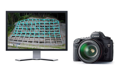
KURABO’s Kuraves-MD is a measurement system for obtaining 3D data of various objects by outputting 3D position coordinates (X,Y,Z) of the objects based on more than one photo taken with a digital camera.
The measurement results can be used for calculating the length, area and volume of the object, creating sectional views, and calculating angles, as well as synthesizing and creating additional drawings by reading 3D CAD data.
■ Mechanism of 3D measurement system
TipsAbout 3D measurement
Tips1.
Triangulation
This measurement technique, as its name implies, uses the fundamental laws of triangles to measure the distance between two points.
More specifically, when the accurate distance between two points is known, the distances between a point in a far distant location and these two points can be established in accordance with the law that a triangle is established once one side and the two angles (the angles formed by the distant point and the two points) at both ends are known. (Fig. 1).
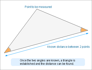
Fig. 1: Conceptual diagram of triangulation
For example, when you want to measure the height of a tree, stand in a location a little distant from the tree. If the distance between you and the tree and the angle formed by line between the standing location and the top of the tree and the ground surface are known, you can calculate the height of the tree. This is also considered to be an application of triangulation (assuming that the angle formed by the tree and the ground surface is 90 degrees) (Fig. 2).
The use of this triangulation principle allows you to measure the three-dimensional shape of an object located in a distant place.
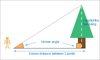
Fig. 2: Measuring the height of a tree
Tips2.
Principles of the pinhole camera
With a pinhole camera, light is passed through a very small hole (pinhole), such as one made by a needle, so that an image is formed on a film or sensitive paper (such as photographic paper) located at a distant place.
When an object is exposed to sunlight or similar light, the light is reflected (scattered) in various directions. Now, take a box and put a pinhole in the outside the box. Among the light beams coming from outside the box, only those in the appropriate direction are allowed to pass through the pinhole, while the others are blocked by the box. When sensitive paper is placed inside the box, the light beam passing through the pinhole forms an image on the sensitive paper. This is the principle that allows you to take a picture with a pinhole camera.
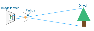
(The image formed here is inverted by 180 degrees.)
Fig. 3: Diagram of pinhole camera
Fig. 4 shows the coordinate relationship between the image formed by the pinhole camera and the actual object.
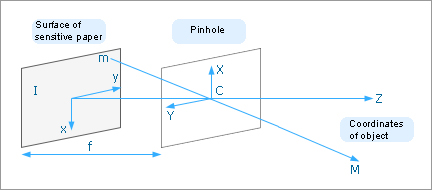
Fig. 4: Pinhole camera as viewed geometrically
For the pinhole camera, plane I indicates the surface of the sensitive paper and distance f the depth of the camera box. A pinhole is made in plane F in parallel with plane I and then an image is taken.

From this relationship, it is found that coordinates m on plane I can be calculated once focal length f and coordinates M of the object are known.
Tips3.
Image formed through lens, distortion of the lens
For regular cameras, lenses are used to form an image rather than a pinhole. Now let’s look at the mechanism of forming an image with a lens (Fig. 5).
When light passes through the lens, it is refracted in a specific direction depending on the incident angle. At this time, the light refracted by the shape of the lens is focused on a spot beyond the lens to form an image. This spot is called a “focal spot”.
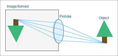
Fig. 5: Diagram of camera using a lens
When an image is formed using a lens, a problem arises from distortion. Fig. 6 shows an image that was obtained when simili paper (on which dots were printed at equal intervals) was filmed using a digital camera (of course, with a lens).
As shown in Fig. 6, the distortion of the lens itself caused lines to be projected as distorted. As seen in this figure, the square shape is distorted like a barrel. This is called “radial distortion”, which becomes more apparent the closer the dots are to the edge.
For a three-dimensional measurement using cameras, which will be described later, this distortion must be corrected beforehand because it greatly affects the accuracy.
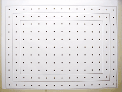
Fig. 6: Distortion due to a lens
Tips4.
Determination of positional relationship between multiple cameras
When shooting from a different angle the object is by using multiple cameras, if reflected in the camera to each point of attention for more than a certain number, we can determine the relative position of the camera from the coordinate information of the point.(Fig.7)
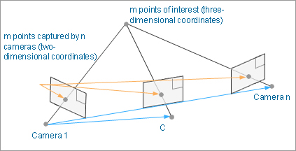
Fig. 7: Specific diagram of camera positions

Now, let’s assume there are m points and n cameras (= n photographs) (in Fig. 7). In this case, 2mn of the above equations can be set up for m points on n photographs.
There are 6n + 3m pieces of unknown information (number of unknown values) (camera positions + directions: 6n; point positions: 3m).
At this point, a coordinate system can be established arbitrarily. So the number of unknown values can be decreased by 6 if the position and direction of one camera are taken as reference coordinates.
In addition, since the scale becomes indefinite geometrically, the number of unknown values can be further decreased by 1. As a result, the total number of unknown values becomes 6n+3m-7.
This means that 2mn simultaneous equations are solved when the number of equations is larger than that of the unknown values.That is,

he following equation must be met:
Assuming that there are 2 photographs (n = 2), the above condition becomes:

Hence, if more than 4 points are commonly taken on 2 photographs, in principle, the simultaneous equations can be solved and the positional relationship between the cameras can be determined.
However, non-linearity is a bottleneck, making it very difficult to solve the equation by using 5 points. Kurabo's “Kuraves-MD” has succeeded in solving the equation by using 8 corresponding points.
Tips5.
Determination of object coordinates using two cameras
5. Based on the method of determining the positional relationship between multiple cameras, use two cameras to film an object. If the positional relationship between the cameras is established, the relationship between a certain point of interest on the object and the image filmed by the cameras is as shown in Fig. 8.
For the point of interest, the point located at the intersection of the line connecting the point filmed by camera 1 to the center of its lens and the line connecting the point filmed by camera 2 to the center of its lens is obtained as the targeted coordinates of interest.
However, only the relative relationship of the triangle formed by connecting cameras 1 and 2 and the point of interest is obtained here. To obtain the absolute scale, a plain scale must be found in at least one place.
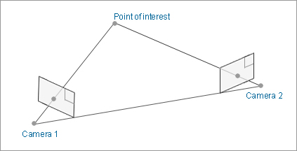
Fig. 8: Specific diagram of three-dimensional coordinates using cameras
Tips6.
Epipolar line (auxiliary line)
The line that connects camera 1 to the point of interest is projected as a straight line in camera 2. This line is called an epipolar line.
The line that connects camera 2 to the point of interest is similarly projected in camera 1.
If the coordinates for the point of interest are unknown, it is known that the point captured by camera 1 is located on this line (epipolar line).
Kurabo's“Kuraves-MD”uses the nature of the epipolar line to display an epipolar line as an “auxiliary line” so that it can be used as auxiliary means of obtaining coordinates.
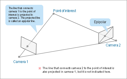
Fig. 9: Epipolar line
Tips7.
Method for measuring 3D images
Making measurements of three-dimensional figures and positions based on images is collectively called three-dimensional image measurement. Various techniques are available for taking these measurements.
The available techniques are roughly classified into “passive measurement” and “active measurement”.
Passive measurements are carried out without irradiating the target object with specific light or radio waves as measurement support. In contrast, active measurements are made by irradiating the target object with light, radio waves, or acoustic waves. The obtained information is used to three-dimensionally measure the object.
| Passive measurement | Lens focal point technique | This technique uses the same principle as focusing by adjusting the focus ring on a single-reflex camera; i.e., measuring the distance between the coordinates for the object and the camera. When the focus is taken at a certain point, the distance is found from the matching point on the scaled dial. This technique requires a lens with a very small focal depth and, therefore, is not suitable for distant measurements. |
|---|---|---|
| Stereo technique | For this technique, a camera is placed on the right and left sides and the triangulation principle is used to make measurements. There are different stereo techniques depending on the layout of cameras, including “binocular”, “trinocular”, and “mobile camera” types. “Kuraves-MD” uses the mobile camera technique. | |
| Active measurement | Light laser technique | In this technique, an object is irradiated with light and the time required for the light to return is measured to obtain a distance image. |
| Active stereo technique | For the active stereo technique, one of the two cameras is replaced by a device that emits light. This technique is further classified into the slit beam projection technique and others according to the type of projected light. * Slit beam projection technique -- A slit beam is projected onto an object and in this state, the object is photographed. The degrees of changes in the beam are detected to make measurements. |
|
| Illuminance difference stereo technique | For this technique, multiple light sources are projected onto a target object. The multiple images that were obtained while the light sources were alternated are used to find the directions of planes. Surface elements on the plane of the object closer to the light source are filmed brighter. So the inclination toward the light source can be measured. Three-dimensional measurements can be made by obtaining such planes. |